THE TYSONS TOWER
FAIRFAX, VA

Building Name
Location
Occupant
Occupancy Function
Size
Number of Stories
Project Schedule
Delivery Method
The Tysons Tower
Fairfax, VA
Undisclosed
Office Building
Primary Occupancy Types: A-2, A-3, B, M, S-2
Accessory Occupancy Types: S-1
1,710,495 sf
3 below grade, 31 above grade
November 19, 2014 to August 31, 2018
CM at Risk with GMP
GENERAL CONTRACTOR


DAVIS/GILFORD

STRUCTURAL ENGINEER
ARCHITECTS


MECHANICAL ENGINEER
DESIGN & FUNCTIONAL COMPONENTS
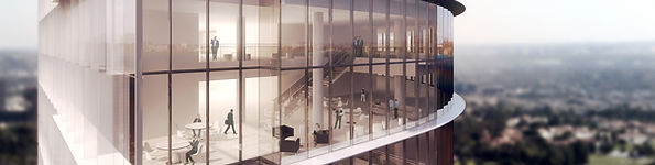
The Tysons Tower provides its occupants with a collaborative work space and climbs to new heights in the DC area, becoming the second tallest structure in the area, next to the Washington Monument. The building’s program is comprised of the following: 3 stories of below grade parking; an 8 story podium which includes additional parking, lobby space, conference rooms, a fitness center, a full size basketball court, and a servery; a 23 story tower which includes typical office space. The main source of egress is through the building’s core; however, occupants may choose a more experiential path from floor to floor through the double height zipper spaces located on the northwest and southeast corners of the tower floors. Each floor contains a stair to the above floor in one zipper space, and a stair to the below floor in the other zipper space. The stair locations alternate from floor to floor, creating a “zipper” up the tower. The building’s exterior is primarily clad in a curtain wall system that seamlessly continues up the 70 ft. mechanical penthouse.
APPLICABLE CODES
2009 Virginia Uniform Statewide Building Code
2009 Virginia Mechanical Code (based on 2009 IMC)
2009 Virginia Plumbing Code (based on 2009 IPC)
2008 NFPA 70, National Electrical Code with VA Amendments in Ch. 27 of the USBC
2008 Virginia Statewide Fore Prevention Code (SFPC)
2007 National Fire Protection Association Standards 10, 13, 14, 20, 72
2005 National Fire Protection Association Standards 110
2009 Fairfax County Code Reference Package
2011 Fairfax Country Public Facilities Manual
ZONING
Fairfax County, VA Zoning: C-3 (Office District)
HISTORICAL REQUIREMENTS
N/A
The east and west sides of the podium are faced with a unitized metal wall panel assembly (W-01) and a unitized metal panel wall screen assembly (W-02). A small portion of the north podium receives a composite metal panel assembly (W-03) over the curtain wall. The north and south side of the podium are faced with aluminum staggered panels (W-04) to provide natural ventilation in the above grade garage levels.
METAL PANELS
CURTAIN WALL
The tower is glazed in an insulated unitized curtain wall system. As seen in Figure 5, there are two types glazing that envelope the tower’s structure. The first glazing type is supported by the structural slab by tying into anchors, which are cast into the slab as seen in Figure 6 and figure 8. The second glazing type is located in lobby and double height spaces; therefore, there the glazing is supported by horizontal steel tubing as seen in Figure 7. Special units, called fly-by units, are set on the northwest and southeast corners of the tower, extending beyond the tower’s base profile.
ROOFING
The podium receives several types of roofing systems. The northeast terrace on level 6 and the roof on level 8 receive a vegetative roof that may contain up to 6” of growing medium and small succulents. The roofing system, as described in Figure 9 and Figure 10, includes the structural slab, hot fluid-applied waterproofing membrane, extruded hi-density polystyrene insulation board (if the space below is conditioned), a 2” drainage board sandwiched between filter fabric, up to 6” of engineered soil, and a 2’-0” gravel perimeter.

FIGURE 7
FIGURE 8
FIGURE 5
FIGURE 6
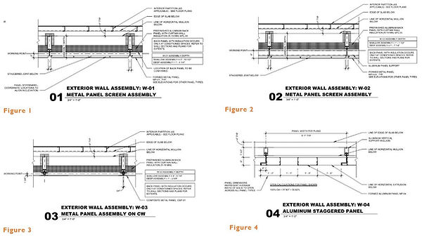
FIGURE 3
FIGURE 4
FIGURE 2
FIGURE 1
The level 7 terraces have a pavers raised on pedestals which sit on a built up slab as shown in Figure 11. These roof terraces also have several planters which contain over 8” of growing medium and small shrubs or trees. The roofing system, as described in Figure 12, includes the structural slab, hot fluid-applied waterproofing membrane, extruded hi-density polystyrene insulation board, a 2” drainage board sandwiched between filter fabric, and more than 8” of engineered soil.
The tower receives a typical bituminous roof system on the structural slab with a vapor barrier, tapered ISO insulation system, densdeck coverboard, and a torch applied bituminous membrane, as detailed in Figure 13.
This building is planned to achieve LEED Gold Certification through its design and construction efforts. By integrating sustainable measures in the design, the building will perform at a more energy efficient level. The implementation of a green roof on level 8 and various terraces will provide additional insulation to the roof system. The project will decrease its mercury footprint by utilizing LED fixtures. During the construction process, the team is taking efforts to closely manage what materials arrive on site and what waste leaves the site. Every subcontractor must complete the required documentation for material manufacturing and harvesting locations, recycled content, certified wood and MSDS sheets for all adhesives, sealants, carpets, paints and plywood per the specifications. In addition, 75% of the waste (by weight) from this project is diverted from a landfills by direction from a third party waste management company. Further LEED analysis may be referenced in Technical Report III.

FIGURE 9
FIGURE 10

FIGURE 12
FIGURE 11

FIGURE 13
CONSTRUCTION
Construction for this project was bought out in two packages: core and shell and tenant interiors. Both scopes of work were awarded to Davis/Gilford for construction. The building is to be completed in 44 months, and is to be turned over in 4 phases: Podium & Tower Levels 9-13, Tower Levels 14-13, Tower Levels 20-25, and Tower Levels 26-31. In order to maintain the intensive construction schedule, interior work began prior to the structural topping out. However, the installation of interior work is dependent on the building being fully enclosed and sometimes require conditioned air. Since the central plant at the penthouse is the main source of conditioned air, several temporary building systems were implemented to allow interior work to begin prior to the structural topping out. Two temporary roofs were installed on levels 11 and 24 . These temporary roofs allowed the building to be fully enclosed in several phases once curtain wall was installed up to the temporary roofs. A temporary AHU located on level 10, supplied by temporary boilers and chillers on the north end of the site, provided hot and cold air to the enclosed spaces while localized dehumidifier units conditioned areas with sensitive finishes. See Figure 14 and Figure 15 for phasing diagrams of the temporary systems. Construction of the building’s main structural system began in the southwest corner and progressed to the northeast corner of the site. A total of six cranes were utilized throughout construction, each servicing the building according to it’s capacity and radius. TC#3 and TC#4 tied into the building’s structure for support and were jacked in 100 foot increments, climbing to the necessary heights to construct the the tower and penthouse. TC#6 was installed in the center of level 31 and acted as the “workhorse” for the penthouse, setting heavy mechanical equipment and structural steel. TC#3 and TC#4 did not have the capacity to lift these items at the end of their reach.

FIGURE 14

FIGURE 15
ELECTRICAL
A 480/277V, 3 phase, 5 wire, feed supplies the building by Dominion Virginia Power. The main feed supplies six 2500KVA transformers and six 4,000A switchgears at the ground level main electric room. Aluminum bus duct transfers the power from the ground level main electrical room to the localized electrical and IDF rooms on each level with great efficiency, resulting in low voltage drops. The localized electrical rooms contain distribution panels and a 120/208V step-down transformer to accommodate lighting and other low voltage devices. The localized IDF rooms, also contain 120/208V step-down transformers.
The level 4 generator room contains three life safety generators and a UPS battery system, which is dedicated to building’s IDF equipment. The central plant at the penthouse contains three switchgears which power the boilers and chillers at 480/277V. The central plant also houses a generator room containing two life safety generators dedicated to levels 29 through 31 and also the penthouse HVAC equipment. A continuous power supply is required for the top two levels (levels 30 and 31) and level 29, which serves as a huddle point for occupants in the event of an emergency
LIGHTING
The lighting for the Tysons Tower includes several types of LED fixtures to accommodate the many different areas throughout the building. The following typical fixtures are used in the spaces listed to the right:
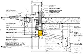
FIGURE 16
Public/Circulation Areas
Lobby
Open Office Areas
Small Conference Rooms
Large Conference Rooms
Special Events Room
Servery
Basketball Gym
Fitness Center
2-Multiple Gimbal Downlights, Recessed Warm LED, 277V
4” Wide Linear, Recessed Warm White LED, 277 V
Adjustable Downlight, Recessed Warm LED, 277 V
4” Wide Linear, Recessed Warm White LED, 277 V
4” Round, Recessed Warm White LED, 277 V
4” Wide Linear, Recessed Warm White LED, 277 V
4” Round, Recessed Warm White LED, 277 V
LED Spotlight with 26° Optics
2” Wide Linear, Recessed Warm White LED, 277 V
4” Round, Recessed Warm White LED, 277 V
LED Spotlight with 26° Optics
4” Round, Recessed Warm White LED, 277 V
4” Wide Linear, Recessed Warm White LED, 277 V
2’x2’ Recessed Warm LED, 277 V
Occupancy sensors are used throughout the building so that fixtures only operate when people are present in the space. Sun shading devices are located at the perimeter along the curtain wall and are used to regulate the amount of sunlight entering the building. Figure 16 shows how the sun shade, highlighted in yellow, is placed at the slab edge.
The penthouse’s screenwall will be covered in LED lights. These LEDs will be programmable so that the tenant may adjust the lighting design.
MECHANICAL
In addition to the central plant located in the penthouse, there are three mechanical rooms that supply the Tysons Tower with conditioned air through an air-water AC system. The primary air-handing-units (AHU) distribute the conditioned air through centralized duct risers in the building’s core to feed local designated-outdoor-air teminal units (DTU). These DTUs are supplied with hot and chilled water through a four pipe hydronic system for localized treatment of the air. The level 2 mechanical room houses one AHU that supplies the six story atrium lobby space. The two AHUs in the level 5 mechanical room and the three AHUs on the level 6 mezzanine supply the amenity spaces on levels 6 through 9. Finally, the central plant houses three AHUs that supply the rest of the tower, levels 10 through 31. The central plant also contains four cooling towers, four 900 ton chillers, and contributory heat exchanges/pumps which supply the building’s coiling coils. It also houses five 6,000 MBH boilers; four of which are active, operating at 50% capacity, while the fifth boiler is at standby; and the necessary pumps to distribute the building’s hot water. The garage levels do not receive conditioned air; however exhaust fans on the below grade levels and the perforated metal enclosure on the above grade levels provide ample ventilation.
STRUCTURAL
A reinforced cast-in-place concrete system is used for the substructure. The exterior foundation walls are formed between a unitized form system and the SOE system, sheeting and shoring. A combination of deep and shallow foundations are used to accomodate the soil conditions and the building’s loading. Spread footings consume the south foundation to provide support for the 3 stories below grade and 8 story podium. The deep foundations, consuming the mid and north sections of the site, are pile caps which sit on 2’-0” in diameter auger-cast piles which extend an average of 47’-0” in depth to reach suitable soil conditions. These piles support both the tower and any potential, future expansion above the 8 story podium. A mat slab also provides support for the tower and contains 2,500 CY of concrete and 460 tons of reinforcement steel. Being greater than 5’-0” in depth, the mat slab was considered mass concrete and required special measures. The structural engineer required the mat slab to have zero cold joints, resulting in a 10 hour continuous pour, utilizing up to 5 concrete pump trucks at a time. The mat slab’s temperature was not to exceed a maximum temperature of 160˚F and a temperature differential of 35˚F. Temperature sensors were tied to the reinforcing throughout the mat slab, providing temperature monitoring throughout the duration of the pour and curing time.
The superstructure is composed of cast-in-place concrete with post-tensioned slabs. This system provides long spans and slabs as thin as 7”, accommodating the amenity and office spaces located within the building. The building’s structural frame transitions from concrete to structural steel at the mechanical central plant located in the penthouse. This system change was implemented to support the heavy equipment loads in the penthouse. The penthouse levels are composed of a 2” steel deck with a 4” topping slab. Finally, the central plant is surrounded by a structural steel screen wall which supports the glazing that encloses the central plant.
Reference Technical Report II for further analysis (including construction means and methods, schedule, and cost analysis) of the structural system.
FIRE PROTECTION
The below grade and above grade garage levels are protected by a dry-pipe system given that they are open to outside air. The rest of the building is protected by a wet-pipe system, with preaction systems installed in the level 04 UPS room and the level 21 telecom head-end room. The 70’ main lobby atrium is protected with high density, K8 sprinkler heads to provide required coverage at the increased ceiling height. There are four fire pumps located in the B1 level fire pump room for the following sprinkler systems: low-zone @ 1250GPM that feeds levels B3 to level 11, mid-zone @ 750GPM that feeds levels 11 to 23, high-zone @ 1000GPM that feeds levels 23 to PH, and back-up @ 1000GPM that can back up either the mid or high zone systems. All pumps are on back-up emergency generator power and required per County code given that the building height is over the maximum height reachable via the current pump truck in the County.
TRANSPORTATION
Building occupants can navigate the Tysons Tower through stairs, elevators, and escalators. There are a total of 11 stairs; The main source of emergency egress is through the 2 stair towers that run up the tower’s core. The remaining 9 stairs provide a means to travel throughout the below grade garage levels and podium levels. The tower levels allow for a more experiential path from floor to floor through the double height zipper spaces located on the northwest and southeast corners. These zipper spaces contain a stair to the above floor in one zipper space, and a stair to the below floor in the other zipper space. The stair locations alternate from floor to floor, creating a “zipper” up the tower. The lobby on level 1 serves as a greeting area and directs all occupants and visitors to the sky lobby located on level 7 where they may go through security and start their route to their destination. There are a total of 28 elevators in the building. A bank of 5 elevators service levels B3 through 7, allowing access to the sky lobby. A bank of 8 low-rise elevators service levels 6 through 19, providing access to the amenity levels and low rise office levels. A bank of 8 high-rise elevators service levels 7 through 31, 4 of which also service level 6, providing access to the high-rise office levels. The remaining elevators function as service and private elevators. Located on the south end of level 3, there is a pedestrian bridge connecting the Tysons Tower to an existing office building, allowing occupants to easily navigate between the two buildings. There are 2 elevators that service levels 3 through 7 near the bridge connection to provide easy access to the conference rooms and servery located on levels 6 and 7. A bank of escalators is also located near the bridge connection that service levels 3 through 6. These escalators were added to the design during construction after an analysis indicated an expected increase in traffic flow from the bridge connection to levels 6 and 7 during conferences.
TELECOMMUNICATIONS
The main telecom service feed runs to the MDF room located on level 21. The MDF distributes data to the localized IDF rooms, which only occur every three levels as they supply telecom data to the floors above and below. The building operates on a ION E DAS (Distribution Antenna System), which provides wireless services. The ION E system allows for operational flexibility based on the building occupants’ needs. All conference rooms are outfitted with display, audio video, and touch panel connectivity.